SSMA Series
Specifications
Electrical:
|
Impedance |
50 ohm | ||
|
|
0 - 18 GHz | ||
|
Working Voltage |
250 VRMS max. | ||
|
Dielectric Withstanding Voltage |
750 VRMS min. | ||
|
VSWR |
Straigh |
1.2+ | |
|
Right Angle |
1.2+ | ||
|
Contact Resistance |
Center Contact |
6 Milliohms Max. | |
|
Outer Contact |
2.5 Milliohms Max. | ||
|
Insulator Resistance |
1000 Megohms min. | ||
Material:
|
Parts Name |
Material |
Finish |
|
Body, Metal Parts |
Brass per QQ-B-626 or Non-magnetic stainless steel per QQ-S-764#303 |
Nickel, Gold or Passivity per requirement. |
|
Center Contacts |
Plug: Brass per QQ-B-626 |
Gold |
|
Jack: Beryllium copper per QQ-C-530 |
Gold | |
|
Insulators |
Teflon |
White |
|
Crimp Ferrules |
Annealed copper |
Nickel or Gold per requirement |
NOTE:Other Material/Finish is Available on
Request.
Mechanical &
Environmental:
|
Engagement Force |
|
|
Disengagement Force |
|
|
Coupling Nut Retention |
|
|
Coupling Proof Torque |
|
|
Contact Retention |
|
|
Durability(Mating) |
500 cycles min.(For Beryllium copper Jack contact only) |
|
|
|
|
Vibration |
MIL-STD-202 Method 204 Test Cond.B. |
|
Salt
Spray |
MIL-STD-202 Method 101 Test Cond.B. |
|
Thermal
Shock |
MIL-STD-202 Method 107 Test Cond.B. |
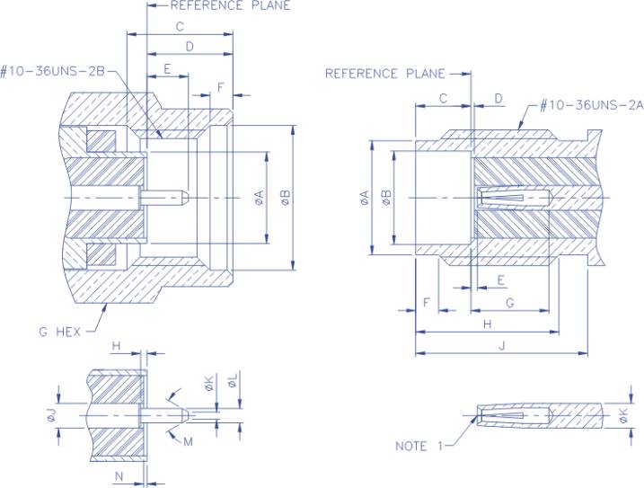
INTERFACE MATING
DIMENSIONS
|
PLUG |
|
|
JACK | ||||
|
Letter |
Millimeters |
|
|
Letter |
Millimeters | ||
|
Minimum |
Maximum |
|
|
Minimum |
Maximum | ||
|
A |
3.15 |
3.22 |
|
|
A |
3.89 |
4.06 |
|
B |
4.98 |
5.13 |
|
|
B |
3.23 |
3.30 |
|
C |
3.30 |
- |
|
|
C |
1.9 |
1.96 |
|
D |
2.54 |
3.38 |
|
|
D |
0.00 |
0.25 |
|
E |
1.27 |
1.65 |
|
|
E |
0.00 |
0.25 |
|
F |
0.38 |
1.14 |
|
|
F |
0.51 |
1.02 |
|
G |
6.23 |
6.47 |
|
|
G |
1.90 |
- |
|
H |
0.00 |
0.25 |
|
|
H |
4.32 |
- |
|
J |
0.86 |
0.88 |
|
|
J |
5.84 |
- |
|
K |
- |
0.25 |
|
|
K |
0.86 |
0.88 |
|
L |
0.50 |
0.53 |
|
|
|
|
|
|
M |
70∘ |
95∘ |
|
|
|
|
|
|
N |
0.00 |
0.25 |
|
|
|
|
|
|
|
|
|
|
|
|
|
|
|
|
|
|
|
|
|
|
|
NOTE
1:I.D. TO MEET VSWR AND CONTACT RESISTANCE
WHEN MATED WITH 0.5/